
EV charger CT clamps: why placement decides how well load management works
What a CT clamp actually measures, where it should go, and what to do when one measurement point is not enough
Almost every smart EV charger feature that sounds impressive on a product page depends on one unglamorous component: a current transformer clamp.
Load management, solar-aware charging, protecting the main fuse, avoiding a tripped supply during a busy evening — all of it rests on the charger knowing how much current is flowing somewhere else in the property. That knowledge comes from a CT clamp, and a CT clamp only knows about the one cable it is clipped around.
Get the placement right and load management is invisible. Get it wrong and the customer sees charging that is slower than expected, sessions that pause for no obvious reason, or solar charging that never quite behaves the way the brochure suggested.
Quick answer: where should an EV charger CT clamp go?
An EV charger CT clamp should normally be fitted on the incoming supply, before the charger's own circuit, so it measures the total property load rather than the charger alone. It must be oriented correctly for current direction and clipped fully closed around a single conductor.
If the site also needs solar, storage or sub-board measurement, one CT position cannot cover every question. That is a site design decision, not a fault.
What a CT clamp actually measures
A CT clamp is a split-core sensor that clips around a single conductor and produces a small signal proportional to the current flowing through it. It does not measure the whole installation. It does not know what an appliance is. It measures one cable, in one direction, at one point.
That has three practical consequences.
It only sees what it surrounds. A CT on the charger circuit tells you about the charger. A CT on the meter tails tells you about the property. These are different questions with different answers.
Direction matters. Most CTs are marked for supply direction. Fitted backwards, the reading can be inverted, and a load can look like generation. This is one of the most common causes of odd load-management behaviour on a newly commissioned site.
One conductor only. A CT clipped around both line and neutral sees close to zero, because the currents cancel. It is an easy mistake in a tight consumer unit, and the symptom is a charger that behaves as if the property is using nothing at all.
Why placement decides the customer experience
Load management works by comparing measured load against a configured limit and reducing or pausing charging when headroom disappears. We covered that behaviour in EV charger load management.
The measurement point defines what the charger is protecting.
| CT position | What the charger can protect | What it cannot see |
|---|---|---|
| Meter tails / incoming supply | The main fuse and whole-property load | Which circuit caused a spike |
| Sub-board or distribution board | A specific part of the site | Load elsewhere on the same supply |
| Charger circuit only | The charger's own draw | Everything else in the property |
| Solar inverter output | Generation available to divert | Import, export or household consumption |
A charger with a single CT on the incoming supply is doing the most important job well: keeping the property inside its supply capacity. What it cannot do is answer the more interesting questions a modern home or small commercial site now asks. How much of this session came from solar? Is the home battery discharging into the car? Which sub-board is close to its limit?
Those questions need more than one measurement point.
The industry pattern: one CT was designed for a simpler house
The single-CT model came from a time when a home had a supply, some appliances and eventually a charger. It was a sensible design for that installation.
The typical UK property that installers now walk into looks different. Solar is common. Home batteries are increasingly common. Heat pumps are arriving. Half-hourly and agile-style tariffs mean the household is actively trying to shift load into specific windows, and the customer is watching the numbers closely enough to notice when something looks wrong.
Meanwhile the useful measurement points have spread out. The meter position, the consumer unit, the inverter and the storage system may be in three or four different places, sometimes with an awkward cable route between them. A long CT tail across a garage or through a loft is untidy at best and fragile at worst.
This is a whole-industry constraint rather than a PlugStream one. Every charger brand that offers solar-aware or load-aware charging runs into the same physical limit: the intelligence can only be as good as the measurement points, and measurement points cost cable.
Where PlugStream Flow fits
PlugStream 7 charge points include a connection for one onboard CT. That covers the common single-measurement install well, and for a lot of homes it is the right answer.
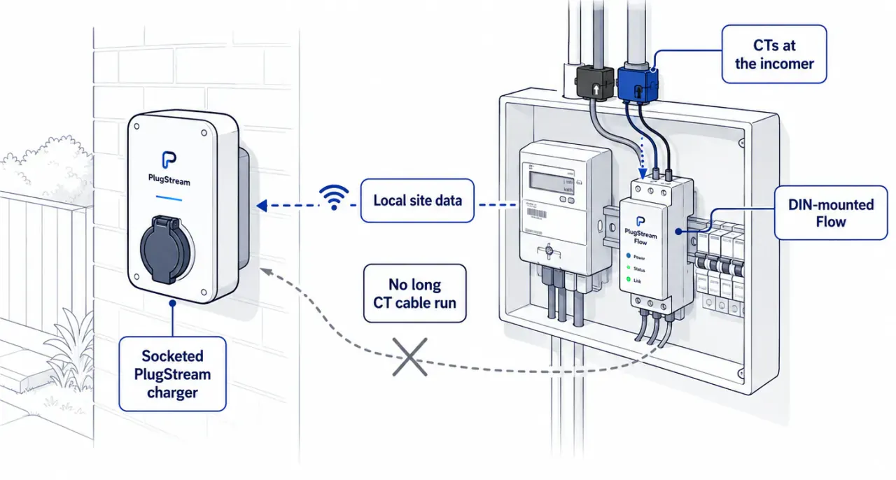
PlugStream Flow is our local intelligence layer for sites that need more than that. It is a sensing node with four CT inputs plus a voltage reference, designed to sit where the measurements actually are rather than where the charger happens to be.
What that changes in practice:
- CTs go where the question is. Grid import and export at the tails, solar at the inverter, storage where configured, a sub-board or a large load on the remaining channel.
- Wireless placement. The node shares its measurements with compatible PlugStream charge points, which removes the long CT run back to the charger.
- One site energy picture. Generation, import, export and charging are easier to reason about when they arrive as one local view rather than four separate guesses.
- Better support evidence. Site events and measurements give PlugStream Sentinel something concrete to work from when a customer reports slow charging, instead of a support conversation built on assumptions.
- More than one charger. Flow kits are packaged around the number of participating charge points, so a two- or three-bay site can coordinate against a shared measurement rather than each charger guessing independently.
Flow does not remove the need for good CT practice. It gives the installer more places to be right.
A practical commissioning checklist
Whether the site uses one onboard CT or a Flow node, the same checks catch most problems on the day.
- Confirm the CT is around a single conductor, not line and neutral together.
- Check the direction arrow or marking against the supply.
- Make sure the split core is fully closed and latched.
- Confirm the CT is on the supply side of the charger circuit if whole-property protection is the goal.
- Turn on a known load and verify the reading moves in the expected direction and roughly the expected amount.
- On a solar site, check behaviour with generation present, not just at commissioning time on a dull afternoon.
- Record which CT is on which circuit. A future support call is much shorter when the roles are documented.
The PlugStream Installer app includes live readings and CT verification steps to make that last part of the job faster, which we covered in PlugStream Installer approved for iOS.
What customers should check before reporting a fault
If charging is slower than expected on a site with load management, the useful first question is not "is the charger broken?" but "what is the charger measuring?"
- Is the property genuinely busy at that moment? An oven, immersion heater or heat pump can consume real headroom.
- Has anything changed on the supply, such as a new circuit or a battery installation?
- Is the reported site load plausible when compared with the meter?
- Does charging return to full speed when the household load drops?
If the reported load looks obviously wrong — zero when the house is busy, or generation when there is none — that points at CT placement or orientation rather than the charger.
Charger Readiness helps separate these cases by making charger-side signals visible before the next charging window, so an expected load-management response is not mistaken for a fault.
Related PlugStream guidance
Start with the wider cluster: EV charging features guide.
Then review PlugStream Flow for site measurement, EV charger load management for the behaviour customers see, Home charging for single-property installs and Commercial charging for multi-bay sites.
FAQ
CT clamp questions
Can an EV charger work without a CT clamp?
Yes. A charger can deliver a fixed current without any external measurement. What it loses is the ability to reduce output when the property is close to its supply limit, and any solar or site-aware behaviour that depends on knowing what is happening elsewhere.
Why does my charger think the house is using no power?
The most common causes are a CT clipped around both line and neutral, a CT that has not fully closed, a damaged or disconnected CT lead, or a CT fitted on a circuit that carries no load. Verify with a known load switched on.
Do I need more than one CT clamp?
Not for a straightforward home install where the only goal is protecting the main supply. More measurement points become useful when solar, storage, a sub-board or multiple chargers are involved and you want to attribute energy rather than just limit it.
Can CT clamps be added later?
Additional measurement points can usually be added as part of a planned upgrade rather than a rebuild. PlugStream Flow CT clamps are specified per measurement point, so a site can start with grid measurement and add solar or storage measurement when that equipment is installed.
Explore More
Compare the PlugStream range
See how PlugStream 7S, PlugStream 7T, and the PlugStream 22 family fit different homes, commercial sites, and daily charging routines.